In this article, we will see 74160 IC you can see 74160 BCD Counter Circuit Diagram. It is a 16 pin BCD counter with a feature of count loading means it is presettable. That means if you want you can count from anywhere between 0 to 9. It is a positive edge triggered IC.
Pin Description of IC 74160:
By using the A, B, C, and D data input pins we can set the output pins QA, QB, QC, and QD to high or low. The active-low clear input resets the IC to 0000. The load enables input (P) enables the count. load input loads data inputs to counter on the positive edge of the clock. Pin 15 is the ripple carry output of this IC, it makes it very easy to cascade multiple ICs to get a higher count.
Features:
- Synchronous counter with the feature of loading
- Two counts enable inputs for n-bit cascading
- Asynchronous reset
- Positive-edge triggering
74160 BCD Counter Circuit Diagram:
What is BCD? BCD stands for Binary Coded Decimal. After number 9 to represent 10 we represent 0 by four zeros and a 1 which means there is no hexadecimal count from 0000 to 1111. IC74160 is useful in decimal counting.
Above is the circuit diagram of the IC 74160 BCD counter, Let’s see the circuit Pins D0 to D3 are not used this time so we have not connected them. A clock input of 2Hz is given at pin 2, pin 1, 10, 7, 15 are connected to logic High. Q0, Q1, Q2, Q3 are connected to the 7 Segment display. This counter counts from 0 to 9 in BCD.
MOD 7 Counter using 74160 IC:
IC 74160 can be converted into a MOD counter by modifying the circuit.
we have connected a three-input NAND gate to the outputs of 74160 IC. The output of the NAND gate remains High and when the count output becomes 111 that is 7 it immediately reset the IC. count 7 is not shown on display. Only 7 numbers from 0 to 6 are displayed on the screen hence it is a MOD 7 counter.
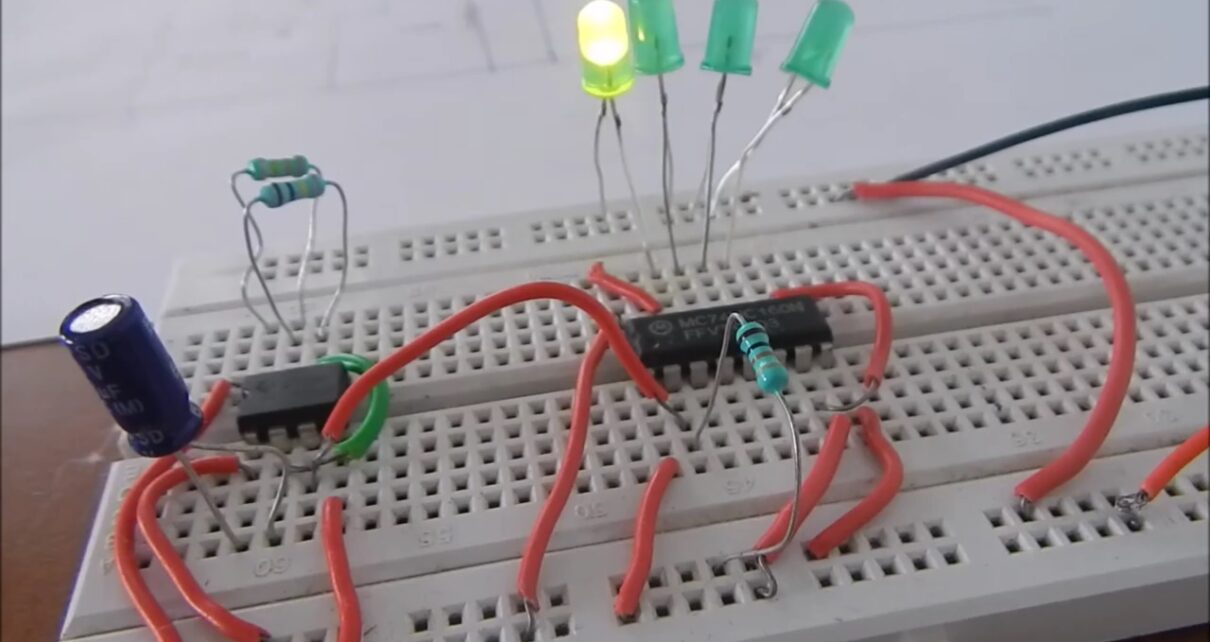
Here is how we have implemented this circuit on a breadboard. We have used a 555 timer IC to provide a clock pulse. To show the output we have used 4 Green colored LEDs. I hope this was helpful to you comment down if you have any queries.


