IC 555 Overview:

The first pin of IC 555 is the ground pin which is a reference voltage for all the internal circuits. Usually, this pin is at zero potential.
The second pin is the trigger pin. When the voltage at this pin is less than (1/3)*Vs then its output will be high.
The third pin is the output pin, it gives square wave output to the circuit.
The fourth pin is the reset pin. When connected to the ground, IC 555 resets.
Pin 5 is the control voltage that controls the threshold and trigger voltage depends on the voltage at this pin.
6th Pin is the threshold voltage when the voltage at this pin is higher than 2/3Vs thus reset the flip flop in the IC 555.
Pin 7 is used to discharge the timing capacitor.
PIN 8 is the supply voltage pin for the whole circuitry in the IC. The supply voltage is 12V.
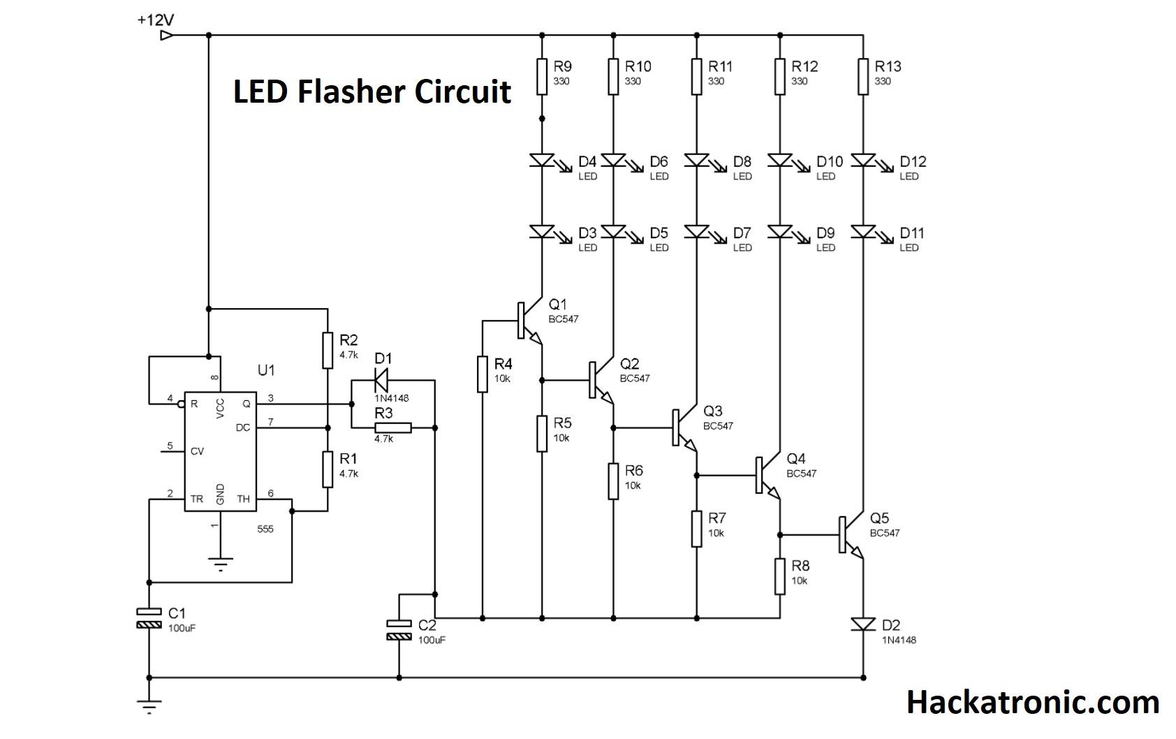
LED flasher Circuit Diagram With 555:

IC 555 is a timer IC that is used to generate time delays. IC 555 is working in astable mode. There are some components needed to generate PWM using IC 555. These are the resistors R1, R2, and capacitor C1. ON and OFF LEDs delay depend on the duty cycle of the PWM which can be varied by varying values of resistors R1, R2, and capacitor C1.
Diode D1 is used in reverse mode to maintain the constant current at the bases of transistors. When there is a high signal at the output of the IC 555, it will turn the transistors ON which make the LEDs glow.
The supply voltage for the whole circuit is 12V. 12V battery is already present in the bikes so there should be no problem with the power supply. Remember that this is only one set that can be used only either for the left signal or the right signal.
Circuit Components for LED flasher:
R1, R2, R3 4.7k (1/4watt)
R4, R5, R6, R7, R9 10k (1/4watt)
R9, R10, R11, R12, 13 (1/4watt)
C1, C2 100uF
D1, D2 1N4148
D3-D12 LED (yellow/orange)
Q1-Q5 BC547 (NPN Transistor)
U1 NE555


Hi,
The 555 timer IC is a highly versatile integrated circuit that can be used to generate a variety of waveforms and time intervals. It is popular with hobbyists and engineers for its low price, simple configuration, and stability.