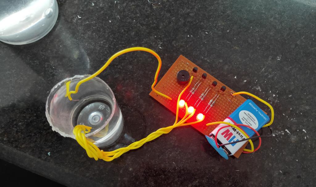
Learn how to make a very simple water level indicator using transistor bc547 at home in a few simple steps as follow…
before starting you should have a basic knowledge of how a transistor works.
watch this video for a better understanding.
Basic principles:
Transistor is a device which is used for amplification or switching of electrical signals.
Here we are using an NPN bipolar junction transistor(BJT) bc547. It has three terminals,
1.) Emitter
2.) Base
3.) Collector

In this project, we will use the switching property of transistors,
which States that,
When we connect emitter and collector of a BJT transistor to negative potential (-) and apply a positive potential to base, current starts flowing from collector to emitter via base if we remove the positive potential from the base then current also stops flowing.
So when a signal is applied at the base the transistor acts as a closed switch and when no signal is applied it acts as an open switch.
Here a fraction of current(<2% of total current) must flow through the base if it does not then it will not work.
Due to some dissolved minerals and impurities, water has some conductivity due to which a very small amount of current(in micro Ampers) flows through it.
To start with your water level indicator mini project you should have the following components and tools.
Components:
1.) BC 547 transistor – 4.
2.) LEDs – 3 red, green, and yellow.
3.) Standard PCB board (or you can use breadboard).
4.) Resistors of 220Ω – 6
5.) Buzzer.
6.) Single-stranded wires.
7.) Soldering iron, soldering wires, and flux.
Circuit diagram
Here is the circuit diagram of the water level indicator using transistor bc547
Construction of the circuit:
In the diagram Q1, Q2.. are transistors with an arrow showing emitter
All the emitters are connected to -ve terminal of the battery and all the collectors are connected to LED ( except 4th which is connected to the buzzer) via 220Ω resistor.
The base of all the transistors is dipped into the water via a 220Ω resistor.
The 4th transistor is used to power the buzzer when the water level rises to its sensor.
Working of water level indicator:
When we power the circuit via a 9V or 5V battery the circuit is in off state there is no current flow through the transistors and the remaining circuit.
When we dip the base terminals of all the transistors one by one in water and also add the+Ve terminal of the battery to water tank, a current in micro Ampers starts flowing via base terminal. This leads to the switching of the transistors to ON state. As the water level in the mug or tank rises the other base terminals also gets connected to the battery via water and thus other LEDs and buzzer finally starts glowing.
This is how the circuit works. We can use it at our house. It’s an amazing DIY project for students. Also, see other applications of bc547 transistor


if i reverse the led connection then only it is working as per video it is not that means