Voltage to current converter is mostly used to transmit signals over a long distance to a control circuit. The most important reason behind it is that while traveling a long distance due to the internal resistance of the wire the voltage gets reduces. if there is a very small signal then it may get lost.
But as we know that current never reduces while traveling a long distance due to Kirchhoff’s current law KCL. That’s why we use current to transmit signals over long distances through wires.
Hence the voltage output of transducers is converted into current. Voltage to current converter is used to transmit the signals from instruments like RTD and thermocouple.
Some of the typical applications of voltage to current converter are in AC and DC voltmeters, diode, LED, and Zener diode testers.
Types of voltage to current converter:
There are mainly two types of voltage to current converter.
- Floating load voltage to current converter
- Grounded load voltage to current converter
Floating load voltage to current converter:
A voltage to current converting circuit is shown in the figure with a floating load RL.
The Input voltage is applied to the non-inverting +ve input terminal of OPAMP. Load resistance RL is connected to the place of the feedback resistor Rf. This circuit is also called a current series negative feedback amplifier.
This is because the feedback voltage across RL is proportional to the output current Io and appears in series with the input voltage.
Apply KVL to the input loop.
Vin = Va + Vp
But as the open-loop gain of this OPAMP is very large
Vd = 0
Vin = Vp
But
Vin = Ri x Io .........as Ib = 0
Io = Vin/Ri
Conclusion:
The input voltage Vin is converted into a proportional output current.
Io = Vin /R1.
If R1 is a precision resistor then we can precisely adjust the output current.
You can simplify any complex circuit using nortorns theorem.
Grounded load voltage to current converter:
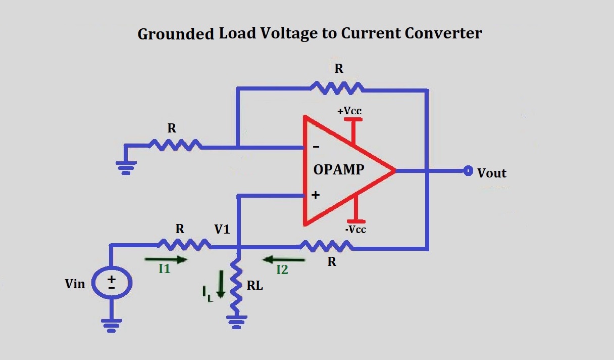
this is another type of bi2i converter in which one terminal of the load is connected to the ground. The V to I converter with ground load is shown in the figure.
Analysis of the circuit:
In this circuit, we have to determine the value of the input voltage at the non-inverting terminal. By using the value of the voltage at the non-inverting terminal will determine the value of load current IL.
Output voltage Vo = (1+RF/R1)*Vin
As all the resistance are of the same value R
Vo = (1+R/R)*V1
Vo = 2V1
Applying KCL
I1 + I2 = IL
(Vin - V1)/R + (Vo - V1)/R = IL
Vin + Vo - 2V1 = IL * R
Vin + 2V1 - 2V1 = IL * R
IL = Vin/R
This shows that the load current IL is dependent on input voltage and resistor R.
This circuit is an important part of sending an analog voltage signal in terms of current over a long distance without losing the information.


