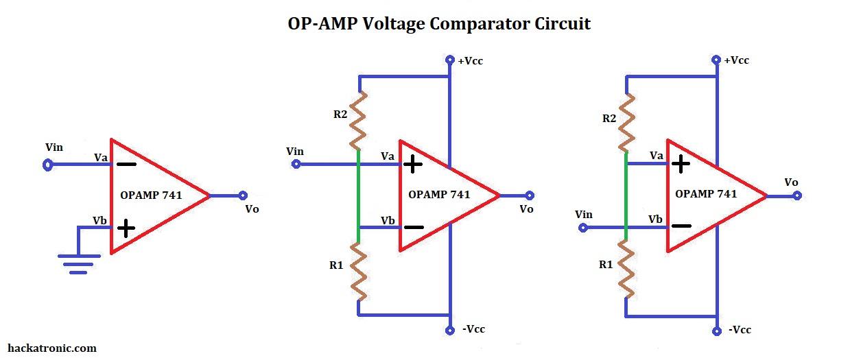
A voltage comparator is a circuit which compares the voltages at its input terminals and switches the output to either high or low depending upon which input was high.
making a voltage comparator using transistors and other components is quite difficult and makes no sense because we have OPAMPs. We can use 741, LM311, LM324, LM393 opamp to make a voltage comparator circuit.
OPAMP Comparator Circuit:
An opamp can be easily configured to act as a voltage comparator.
A voltage comparator based on opamp is shown in the figure. A voltage comparator can be of two types either inverting type or non-inverting type. This is determined by whether the input voltage is given to the inverting terminal or noninverting terminal.
Types of opamp comparators:
Based on the input terminal and output waveform there are two types of opamp voltage comparator
NON-INVERTING opamp comparator:
From the above circuit it can be seen that the reference voltage is applied to the inverting terminal using a voltage divider circuit and input is given to the non-inverting terminal.
In the noninverting comparator, the reference voltage applied to the inverting input terminal, and the voltage which is to be compared is given to the noninverting input.
The output of the comparator is in phase with the input terminal signal.
Inverting opamp comparator:
In inverting comparator, the reference voltage is applied to the non-inverting input terminal and voltage which is to be compared is given to the inverting input terminal just opposite.
The inverting comparator is exactly opposite of non-inverting comparator. The reference voltage is given to the non-inverting terminal and input signal to inverting terminal.
Working of voltage comparator circuit:
Whenever the input voltage Vin goes about the reference voltage the output of the opamp switches to +Vcc.
Inside the opamp, there is a differential amplifier circuit that amplifies the difference between the two input terminals. Since there is no feedback involved when the opamp acts as a comparator. It amplifies the difference between the two inputs to the maximum which is its supply voltage.
The output may be unipolar or bipolar depending on whether the opamp has a dual supply or single rail supply.
Characteristics of a good comparator circuit:
1. Operation speed:
The speed of operation of a comparator circuit should be very high so that it can respond immediately if there is an instantaneous change in the input signal.
2. Accuracy:
the accuracy of a good comparator depends upon the following characteristics High voltage gain:
the voltage gain of a comparator should be very high enough so that if there is a very small input it gets easily amplified to the maximum saturation voltage.
High common-mode rejection ratio (CMRR):
when the common-mode rejection ratio of a comparator is high it can easily reject the noise coming to its input terminals.
Very small input offset current and input offset voltage:
The input offset voltage and current should be small so there is no requirement to compensate for it.
Applications of comparator circuit:
- Analog to digital converter circuit.
It converts analog signals like voice into digital signal (in the form of 0s and 1s)
- In precision rectifier circuits.
In a conventional diode rectifier, there is a voltage drop and some distortion, but this problem can be solved by a precision rectifier.
- Zero crossing detector.
A zero-crossing detector is nothing but sine wave to square wave converter.
- Window detector.
A window detector is a combination of inverting and non-inverting opamp comparator.
- Time marker generator.
It is used in oscilloscope.
- Phase detector.
It is used to detect the phase difference between two signals by their arrival times.
- Schmitt trigger circuit.
A to D converter


