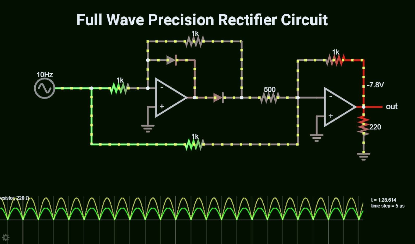
The precision rectifier is a type of rectifier that converts the AC signal to DC without any loss of signal voltage. In a precision rectifier circuit using opamp, the voltage drop across the diode is compensated by the opamp. In a Diode voltage drop is around 0.6V or 0.7V. Also, this circuit can be made to have some gain at the output of the amplifier.
A rectifier circuit is an electronic circuit that converts alternating current AC to direct current DC by allowing it to flow through only one direction. The precision rectifier is also known as a super diode because it has 0 forward voltage drop.
Rectifier Circuit types and working:
A rectifier circuit may be of two types, half-wave rectifier, and full-wave rectifier. In labs, we may use a half-wave rectifier but in practical, full-wave rectifiers are mostly used because they deliver higher efficiency.
The full-wave rectifier is of two types, center-tap rectifier and bridge rectifier. The center tap rectifier uses a center-tapped transformer. Whereas a bridge rectifier uses four diodes making a bridge for current to pass.
As we know that for a normal silicon diode there is a 0.6V to 0.7V forward voltage drop.
So in the case of a center tap transformer, the output gets reduced by around 0.7V. In the case of a bridge rectifier, the output voltage gets reduced by 1.4V because two diodes are used at one time to conduct current.
So if we are dealing with high voltage then 1.4V 0.7V will not make any sense. But if we are dealing with small voltages and small signals which are of the order of 1-2 volt or less than 5 volts then this difference matters a lot.
Peak Detector Circuit using OPAMP
To overcome the voltage drop we use a precision rectifier circuit. In this article, we will be seeing a precision rectifier circuit using opamp. In a precision rectifier, the operational amplifier is used to compensate for the voltage drop across the diode.
Watch this video for better understanding
half wave precision rectifier circuit using opamp:
In this circuit, we are using an opamp (for example LM741opamp and LM358 opamp) in inverting configuration mode. So, in inverting amplifier mode the output of the opamp will be 180° output phase with respect to the input signal. This phase reversal is necessary in order to make both the positive and negative half-cycles one sided. Since we are using an opamp for rectification we can adjust the gain of output very easily.
In the above circuit, we have used an opamp in the inverting configuration. A Diode is connected to the output of the opamp. An input resistor is connected before the inverting terminal. A feedback resistor is connected between the output and inverting terminal.
Working of a precision rectifier circuit:
Negative half-cycle:
In the negative half cycle, the output diode becomes forward biased and the current passes through the feedback resistor to output. As the amplifier is in inverting configuration output voltage is 180° out of phase with respect to input and we get an inverted wave.
Positive half-cycle:
In an ideal OPAMP when the positive half cycle of the input signal is applied to the inverting terminal the output remains low. This happens because the output connected to the opamp becomes reverse biased due to the applied positive input voltage and stops the current.
But in a practical circuit, there is an output voltage due to the feedback resistor.
In order to eliminate this undesired behavior, we add one more Diode in the feedback path.
Modified Precision Rectifier Circuit:
Now the circuit looks like this. Here we have a Diode connected in the feedback path. So when the positive half cycle of the input signal is applied to the inverting terminal, instead of passing through the feedback resistor the current passes through the Diode. At the output, there is a 0V potential so the Diode connected at the output of opamp produces a negative -0.7V potential which blocks the current through the feedback resistor. This is how the undesired output during the +Ve half cycle of input is discarded.
Full wave precision rectifier circuit:
In a full-wave precision rectifier circuit, we add one more summing amplifier at the output of the precision rectifier circuit. This summer adds the negative half cycle of input with the output of the precision rectifier circuit. As it is in inverting configuration the output of the summing amplifier gets inverted and becomes positive.
In the above circuit, we have used a 500Ω resistor to give output of the precision rectifier to the summing amplifier. The value is chosen half the value of the feedback resistor.
Let’s say if the input voltage is 2V and the output of the precision rectifier circuit is -4V after amplification. So at summer, this voltage will be added with the positive half cycle of input. Then it will become -4 +2 = -2. This is done in order to make the amplitude of the output same.
You can use LM358D dual opamp IC to make a precision rectifier circuit. It will work fine for low to medium frequency range.
Applications of precision rectifier circuit:
very useful for high-precision signal processing.
With a few modifications, it can work as a peak detector.


