A current to voltage converter circuit produces output voltage with respect to input current. An I to V converter is used to convert varying current into equivalent output voltage. This circuit is very much useful when the measuring instrument can measure only voltages not the current and we want to measure the output current. The best example is measuring current through a circuit using Arduino. Here the Arduino can measure only analog voltage, so we need a current to voltage converter to do that.
such circuits are used in Data Acquisition Module (DAQ). we can do this current to voltage conversion by a voltage divider circuit if the input impedance of DAQ is high enough. But if the input impedance of DAQ is low then we must use this circuit for impedance matching.
Please do read operational amplifier (opamp) working principle for better understanding.
Circuit Diagram of I to V converter using opamp:
Circuit analysis of Current to voltage converter:
The above circuit is a simple current to voltage converter,
The non inverting terminal is grounded, and the inverting terminal is connected to a current source.
current to voltage converter formula:
now see the current flow in the circuit, analyzing the circuit using Kirchhoff’s current law.
- Applying KCL at node B which is at inverting terminal of opamp we get
Ix - I - Irf = 0
- Also current flowing into the input terminal of opamp is almost equal to zero, hence
Ix = Irf
- This current flows through the feedback resistor Rf which creates the output voltage Vo which is given by Ohm’s law.
Vo = Ix . Rf
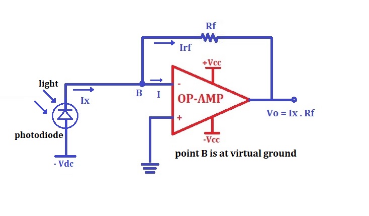
current to voltage converter photodiode:
One example of such an application is using the photodiode sensor to measure light intensity. The output of the photodiode sensor is a current which changes proportional to the light intensity. Another advantage of the opamp circuit is that the voltage across the photodiode (current source) is kept constant at 0V.

One of the most important applications of I to V converter is as photodetector amplifier to measure the intensity of light as shown in diagram. Also, the voltage across the photodiode is kept at 0V due to virtual short.
A photo diode which is reverse biased. Point B i.e. the inverting terminal of the OP-AMP is at virtual ground potential and a negative voltage Vdc is applied at the anode of the photodiode.
When the light is focused on the reverse biased photodiode, a photocurrent Ix starts flowing it is proportional to the intensity of light falling on photodiode as shown. This current acts as the input current to the I-V converter.
Hence the output voltage proportional to photocurrent is produced.
Vo = RF.Ix
In this way the I to V converter provides amplification to the small photocurrent Ix.

