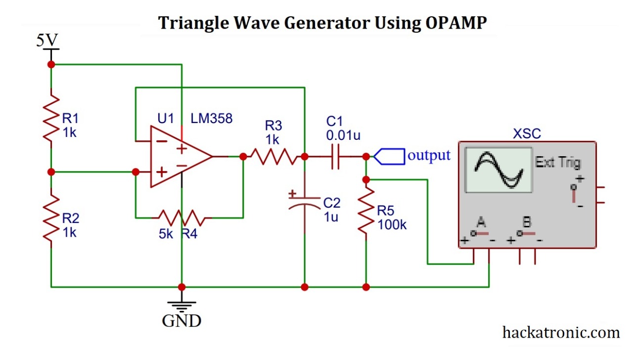
In this article, we will discuss how we can make a triangle wave generator using opamp. So, let’s start discussing how to make a triangle wave generator. A triangle wave is consisting of a constantly rising and falling slope. An opamp integrator gives a triangle wave.
If you are an electronics student then you might have come across the term function generator, sine wave, square wave, triangle wave sawtooth wave, and many more. A function generator is an instrument which is used to generate various types of the waveform of desired frequency and voltage depending upon the requirements of our experiments.
If you don’t know about opamp then please do check outworking of opamp as comparators.
you can also make a triangle wave generator using 555 timer. It is a little easier to make this circuit as compared to opamps.
In this project we will be using LM358 opamp this is a dua opamp package IC. Few resistors, capacitors, and power supply. To see the output, you must have an oscilloscope. Otherwise, you can simulate this circuit on any software, it will work fine.
Circuit Diagram of triangle wave generator using opamp:
Circuit components:
LM 358 or any equivalent opamp like LM741, LM393, or LM324 opamp.
Three 1k ohm Resistors
A 5k resistor (you can use a potentiometer here)
100k load resistance
One 0.01uf capacitor
A 1uf capacitor
Power supply
Oscilloscope to see the waveform.
Circuit Diagram explanation:
LM358 opamp IC is used to make the triangle wave. A voltage divider circuit is connected to the non-inverting input terminal of the opamp. It keeps the terminal input voltage half the supply. Whereas the non-inverting terminal is connected to the output terminal via a resistor of 5k to 10k or a potentiometer.
The output of the opamp is given to a capacitor of 1uf this capacitor continuously charges and discharges to make a triangular output.
The output is the AC coupled using a 0.01uf capacitor to avoid any DC value. A 100k load resistor is attached at the output of capacitor 1.
Working of the triangle wave generator using opamp:
This circuit is a relaxation oscillator with a single opamp working as a comparator.
Initially, the capacitor C2 is not charged, hence the inverting input terminal is at 0 volts. Thus the output of the opamp comparator is high. Due to this, the capacitor charges slowly towards Vcc. As the capacitor voltage crosses the non-inverting input terminal voltage, the voltage at the inverting terminal becomes more than the non-inverting terminal voltage. This makes the opamp output low and the capacitor starts discharging.
When the output of opamp becomes low the 5k and 1k resistor of voltage divider come in parallel to further reduce the reference voltage.
The output produced is then AC coupled via capacitor C1 to remove noise and DC components. This output can be further amplified for further use.
Output waveform of the circuit:
See the output waveform produced by this circuit. This waveform not completely looks like a triangle wave. If you carefully observe, it looks slightly curved. It happens due to the charging and discharging properties of a capacitor.
So this is a simple triangle wave generator circuit using opamp


Pls, i need help, i’m working on 100watt class d audio amplifier, pls I need u guys to guide me and help me out with the circuit diagram and i also need a triangular wave generator circuit of 250khz frequency, I need reply pls
Hi sir,
What resistace acts to descharge the capacitor in this circuit? and how to accelerete or to make low descharging of the capacitor?
Joseph
Try changing values of resistors R3 and R4