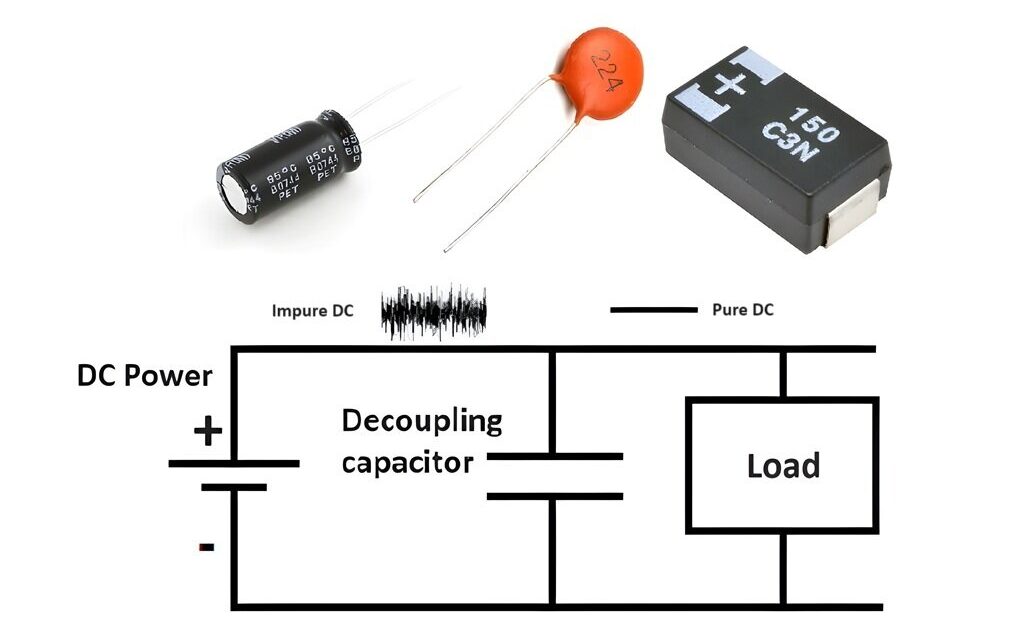
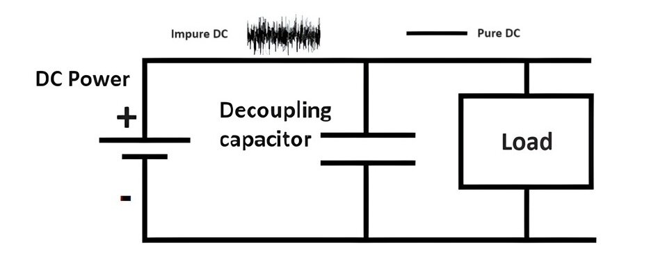
A decoupling capacitor is a capacitor used in electronic circuits to decouple one part of a circuit from another. It serves two primary functions:
- Filtering out Noise: It filters out high-frequency noise or transients on the power supply lines.
- Stabilizing Voltage: It provides a local reservoir of charge to stabilize the voltage supplied to an integrated circuit (IC) or other active device, ensuring reliable operation.
A decoupling capacitor offers infinite reactance to DC signal and does not allow it to pass through. Whereas the reactance of decoupling capacitor for AC signal is far less, it allows AC signal to pass through it. It is opposite of coupling capacitor.
Working of Decoupling Capacitor:
Basic Operation:
Filtering High-Frequency Noise:
-
- Electronic circuits, especially digital ones, can generate noise and high-frequency transients due to switching actions (e.g., in microcontrollers, processors).
- The decoupling capacitor provides a low impedance path for high-frequency noise, effectively shunting it to ground and preventing it from affecting the performance of sensitive components.
Voltage Stabilization:
-
- During operation, ICs and other active components draw varying amounts of current, which can cause voltage fluctuations on the power supply lines.
- The decoupling capacitor acts as a local charge reservoir, supplying or absorbing current as needed to maintain a stable voltage at the IC’s power pins.
Placement in Circuits
Proximity to ICs:
Decoupling capacitors should be placed parallel to power supply and load. It should be placed as close as possible to the power supply pins of the ICs or other active components. This minimizes the inductance and resistance in the path, enhancing the capacitor’s effectiveness in filtering noise and stabilizing voltage.
Multiple Capacitors:
Often, multiple decoupling capacitors of different values are used in parallel. This combination allows for effective noise filtering over a wider frequency range:
- Small-value capacitors (e.g., 0.1 µF or 0.01 µF) are effective at filtering high-frequency noise.
- Larger-value capacitors (e.g., 10 µF or 100 µF) are better for stabilizing lower-frequency fluctuations.
How to Select a Decoupling Capacitor Values?
High-Frequency Noise (MHz to GHz):
Use small ceramic capacitors (e.g., 0.01 µF to 0.1 µF) to filter high-frequency noise.
Medium-Frequency Noise (kHz to MHz):
Use medium-value capacitors (e.g., 1 µF to 10 µF).
Low-Frequency Noise (Hz to kHz):
Use larger electrolytic or tantalum capacitors (e.g., 10 µF to 100 µF) for power supply stabilization and filtering lower-frequency noise.
Parallel Combination
Combining capacitors of different values in parallel can cover a wider frequency range effectively. For example, a 0.1 µF ceramic capacitor in parallel with a 10 µF electrolytic capacitor.
Example of Decoupling Capacitor:
Consider a microcontroller circuit powered by a 5V supply. The microcontroller switches rapidly between different states, causing sudden spikes in current demand, which can lead to voltage dips and noise on the 5V line.
Without Decoupling Capacitor:
- The power supply line directly connects to the microcontroller.
- Voltage fluctuations and noise can interfere with the microcontroller’s operation, potentially causing erratic behavior.
With Decoupling Capacitor:
- A decoupling capacitor is placed between the 5V supply and ground, close to the microcontroller’s power pins.
- During a sudden current spike, the capacitor provides the necessary current, smoothing out voltage dips.
- High-frequency noise is shunted to ground by the capacitor, maintaining a stable voltage supply to the microcontroller.
What type of capacitors are used in decoupling applications?
Tantalum, ceramic and aluminum electrolytic capacitors can be used for decoupling.
What is the difference between decoupling and bypass capacitor?
A bypass capacitor is used to shunt high-frequency noise away from a power supply line to ground. A decoupling capacitor is used to isolate or decouple one part of a circuit from another. Basically, it removes AC signal from DC Signal, stabilizes a device’s voltage supply by mitigating voltage spikes and dips caused by other circuit elements.
How to Test Capacitor?
Testing a capacitor can help determine if it’s functioning correctly or if it has failed. Here are some quick methods to test a capacitor using a multimeter:
- Digital Multimeter with Capacitance Measurement: Measures the capacitance directly by multimeter and compares it with the rated value.
- Digital Multimeter without Capacitance Measurement: Measures the charging behavior of the capacitor by observing the change in resistance with charge.
Summary:
A decoupling capacitor is an essential component in electronic circuits used to filter out high-frequency noise and stabilize the voltage supplied to ICs and other active components. By providing a low-impedance path to ground for noise and acting as a local energy reservoir, it ensures reliable operation of the circuit. Proper placement and selection of decoupling capacitors are crucial for effective noise suppression and voltage stabilization.
What is Coupling Capacitor, Construction, Working & Applications